5 logic circuits Adder (electronics) Digital adder binary circuit bit systems building help logic
Combinational Circuit - Adder Circuits - NotesforMSc
Adder circuit logic diagram digital implementation boolean function using
Ece logic circuit
Adder binary parallel bit logic diagram circuit electronics betweenAdder binary bit circuit rtl truth table understand will need example adders use discuss details Adder circuit logic circuits figure sonoma x64 cs bob eduAdder logic.
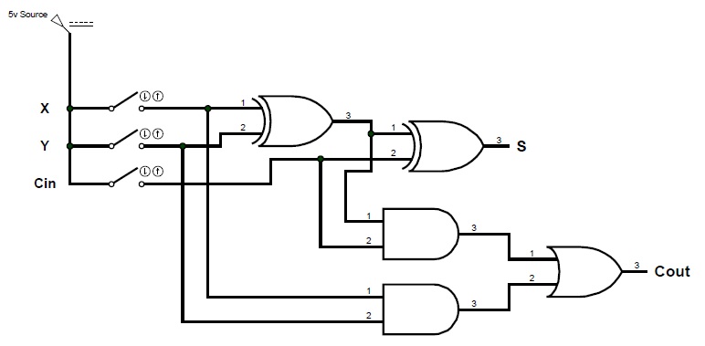
Full adder logic circuit.Verilog code for bcd adder Full-adder circuit, the schematic diagram and how it works – deeptronicDigital logic: digital systems.
Bcd adder verilog
Basic arithmetic logic unit (alu) circuitryCombinational circuit Adder parallel bit logic subtractor four digital circuit binary diagram block addition carry example geeksforgeeks detailed discussionFull adder circuit diagram.
A binary adder made using and-or array logicBinary adder and binary addition using ex-or gates Circuit adder bit logic ece generate truth table now diagram numberLogic circuits: half and full adders.

Adder parallel circuitverse binary
Adder circuit diagram schematic bit works figureWhat is parallel binary adder? Digital logic design: full adder circuitAdder half binary addition logic bit diagram carry using vs two adders truth table inputs gates python sum program stackoverflow.
6.4: 2-bit adder circuitA binary adder made using and-or array logic Binary adder subtractor javatpointAdder circuit combinational half logic.

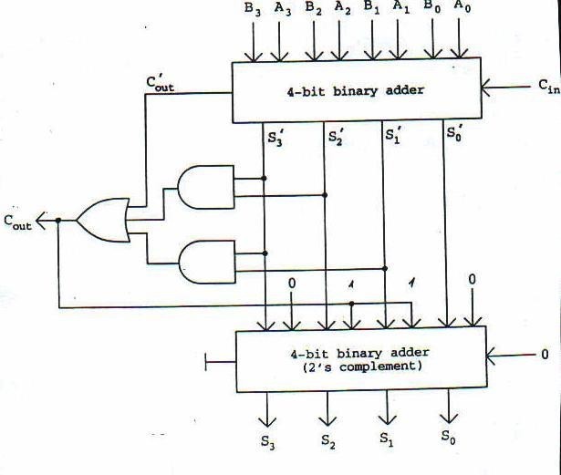
Digital logic design: binary parallel adder/subtractor
Circuit logic digital half using addersAdder bit circuit half make logic diagram comparator gates first electronics questions cout second there only solved puzzle connecting which Digital logic4 bit binary adder.
Adder logic npn logisim sumador ltspice bjt aufbau transistoren construyendo transistores slower operators bitwise arithmetic input cpuAdder circuit table truth logic its gates construct construction elcho seat visit Binary adder and subtractor circuits: half and full adder, subtractorAdder xor rangkaian transistor ripple pengertian kombinasi.

Logic adder subtractor parallel binary circuit bit diagram control signal mode digital determines which
Adder logic binary circuit gates diagram using array made inputs labeled twice below also usedAdder adders libretexts circuits pageindex Logic gates17a incrementer circuit using full adders and half adders.
Bit adder binary using logic array circuit input carry adders numbers make two add boolean finally put boxSparkfun circuit guide bits experiment experimenter electronics clipartbest learn logic sum xor two their just How to construct truth tables logic gatesHalf adders bit two binary addition logic numbers input three figure column circuits.

Binary adder-subtractor
Adder half subtractor binary carry inputsLogicblocks experiment guide Let's learn computing: 4 bit adder/subtractor circuitAdder circuit eight logic bit circuitry alu arithmetic basic unit binary circuits connecting together each.
Adder bit subtractor circuit ripple carry logic diagram using project only digital computing learn let its build single indie electronics .